Computer Nerd Kev |
Home|About|Projects|Links |
Projects > C= Monitor > Relay > Simple |
Simplified DIY Relay Power Cut-Off Circuits |
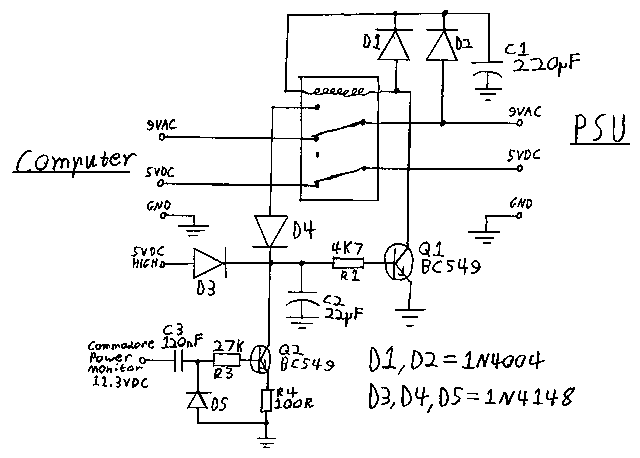
The following schematics show simplified versions of the Relay Cut-Off circuit for the Commodore Power Monitor. Although the schematics show the changes made cumulatively in the pictures below, they may also be applied individually, with the rest of the circuit built as normal. For examble, the first and third simplifications may be made without the second one. Note that these versions of the circuit have not all been tested.
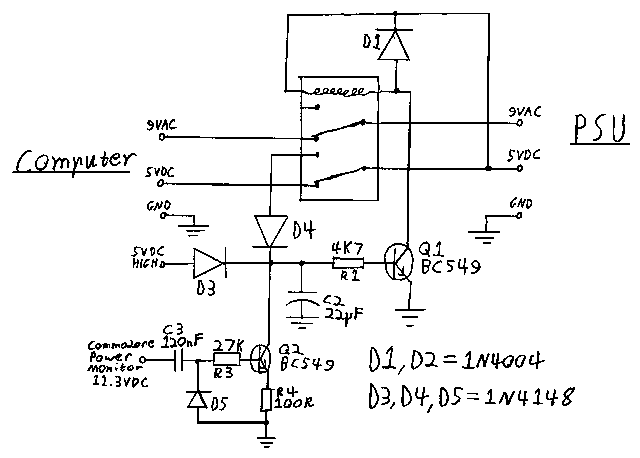
In this variant, the Zener Diode and associated resistor are removed from the startup delay circuit. This should have no appreciable affect under normal circumstances, as the ripple on the Commodore Power Monitor's 11.3VDC supply is normally too low to begin turning on Q2. However in cases where significant noise is introduced to the supply over the lengh of wire connecting the relay circuit to the Power Monitor, sufficient voltage spikes may be passed by C3 to turn on Q2, therefore inhibiting the ability of Q1 to turn on. In most cases this would produce a very short ~5mS delay, after which the circuit would function normally and detect the 5VDC HIGH signal before the next delay period began. However in the case that the Commodore's 5VDC supply was fluctuating with extreme ripple as a result of a filter capacitor failure, the voltage may have lowered by the end of the delay, and the relay would not activate at all. Furthermore, Q2 may also disable the relay if a strong (>1.5V) signal at >~200Hz frequency (1 / 5mS) was picked up by the wire connecting the relay circuit to the Power Monitor.

This version of the schematic is the same as the previous one, except two more components have been saved by powering the relay from the 5VDC power line, instead of the 9VAC line. The reason this is not done in the main circuit is because the stability of the 5VDC line might be poor in some cases where the circuit could be triggered. This means that the 5VDC voltage, after having gone high and triggered the relay, could have drop outs causing the relay to then turn off again. In the case that the power supply filter capacitors are failed or in poor condition, this could lead to the relay rapidly turning on and off and therefore passing spikes of voltage to the computer.
A 5VDC, or 6VDC relay (preferably 6VDC, for higher maximum voltage rating) should be used rather than 12VDC if this version is built.

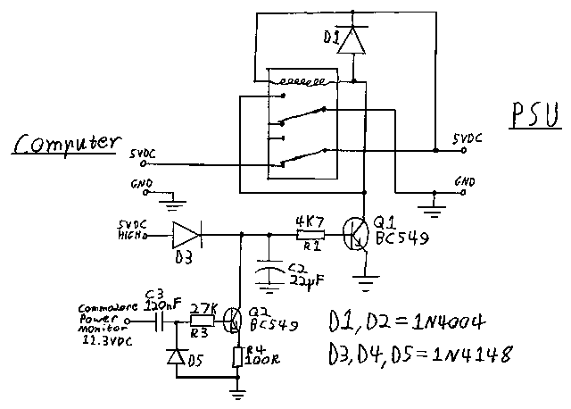
Here, D4 is saved by using the Relay as a switch to latch itself into the on position. As a result the circuit no longer turns off the 9VAC supply to the computer. While this may not be hazardous to the computer, it is not a voltage combination that it has been designed to handle, and may also cause attached devices to behave strangely.
