Computer Nerd Kev |
Home|About|Projects|Links |
Projects > Reflow Controller |
Surface Mount Reflow Oven Controller |
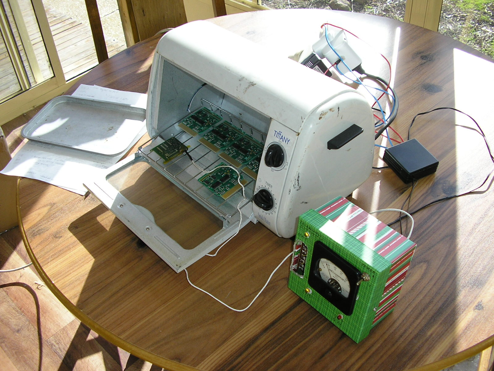
There have been plenty of surface-mount reflow oven controller projects published online and in magazines, most intended for use with toaster ovens. This is also for use with a toaster oven, but unlike other designs I decided to go with a minimal circuit using digital logic. Conventionally a microcontroller uses PID algorithms to compute the duration that the heating elements in the toaster oven are turned on/off in order to control the temperature of the boards inside over the various heating stages for surface-mount reflow. But this really just boils down to something more or less equivalent to low-frequency PWM. So here a NE555 PWM generator circuit has been modified to allow it to advance over four stages of the solder reflow profile, by using a digital counter to select sequential trimpots which are used in the 555 oscillator's RC timing circuit.
My original design for this required a few minor modifications, and last year I updated the schematic and veroboard layout. However I never got around to writing this page for it, and now I'm not entirely sure that I checked everything fully. So even though my build works fine, I suggest checking for any mistakes, and let me know if you find one.

Schematic. Note that the LM741 Op-Amp IC that buffers the output of thermocouple amplifier IC1 should be marked as IC6, not IC5.
It was decided not to use any feedback from the thermocouple amplifier into the PWM timing circuit. The principle is that the settings of trimpots VR1-VR4 should perform repeatable results without any feedback. Obviously this doesn't account for variation in the starting temperature. In practice though I have found that turning the controller, and therefore the oven, on briefly until it reaches around 20-30°C, then turning it off and on again to restart the sequence, is sufficient to get repeatable results at lower starting temperatures that what it was calibrated at.
The thermocouple amplifier and voltage regulator aren't included in the veroboard layout below, these circuits are simple enough that they can be hooked up easily based on the schematic without any pre-planning. The voltage regulator could also be omitted (while retaining 22uF filter cap. C9) if a regulated 12VDC plugpack is used, whereas I used an old unregulated 15VDC transformer plugpack. The thermocouple amp. is based on an AD595 thermocouple amplifier IC which includes an internal zero reference and basically takes care of all the complexities in providing an accurate output voltage proportional to the temperature of the thermocouple. It is quite expensive, but for this I found a cheap/dubious one purchased from a Chinese seller on Ebay to work well enough. The red LED connected between pin 12 and Vcc lights if the thermocouple connection is broken, which would cause false readings. As I used an old analogue panel meter which required 16mA for full-scale deflection, the AD595 output needs to be buffered by a 741 Op-Amp which can supply this much current. I can't entirely remember what the 6.2V zener diode is there for, but I'm sure it's all very clever. R9 sets the full-scale current in combination with the meter's own 50ohm resistance and will need to be adjusted for use with other panel meters.
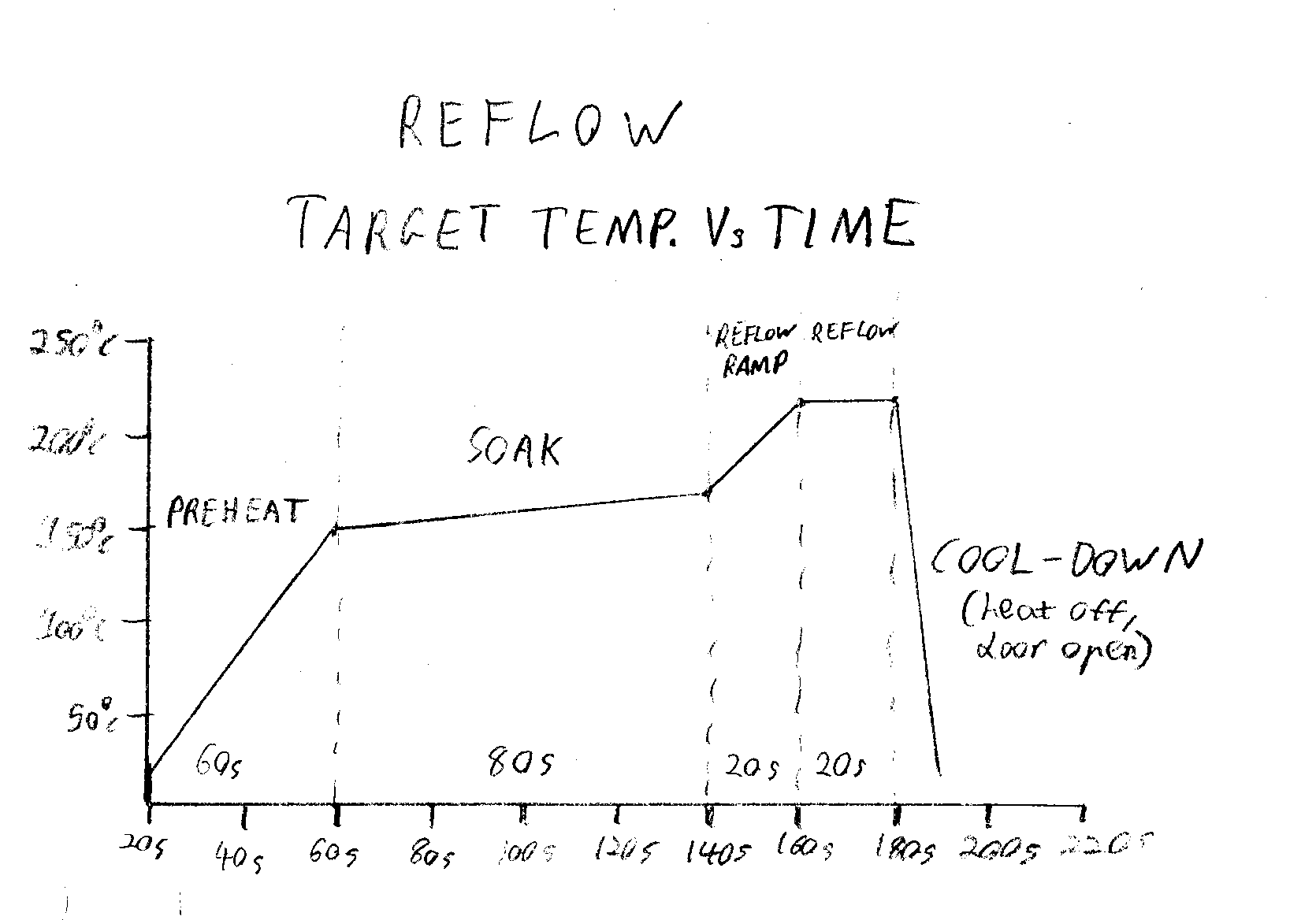
The interesting bits are IC2-IC5 and associated circuitry. The timing sequence for the four stages of the reflow profile shown in the graph above are controlled by decimal counter IC3 (4017). This is clocked by the oscillator IC2, at a frequency of roughly 0.05Hz (one pulse every 20 seconds) but which can be varied by VR5. Multiple counter outputs are ORed together using diodes D1-D7 so that the first two stages will last for multiples of 20s (60s for preheat, and 80s for soak), while the last two can be used directly because they are only 20s long. These outputs connect to IC5, a 4066 quad analogue switch IC each segment of which will connect its associated trimpot within the PWM oscillator's (IC4, NE555) timing circuit when its control signal goes High. These trimpots are previously manually adjusted to set the On time, and there the rate of heating, of the toaster oven for that stage in the reflow cycle. As such, the counter can control the rate of heating over the different stages in the reflow process, and thereby follow the heating profile shown in the graph.
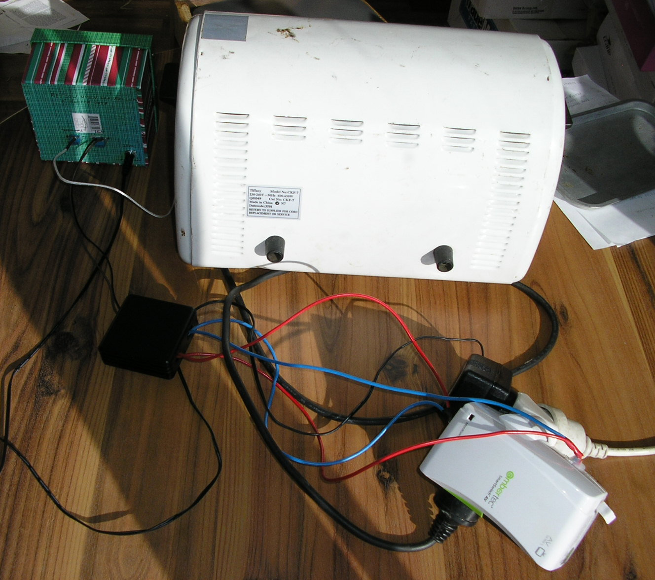
A 12V relay is used to connect power to the toaster oven. I chose to connect this relay externally, and it is in the black plastic box that switches power to a socket in the (also separate) white case (the remains of a TV power-saving device which I harvested for parts).
When the end of the sequence is reached, the Q9 output of the counter (IC3) goes High, turning on NPN transistor Q1 which pulls Low the Reset pins of both 555 timer ICs, turning off the toaster oven and stopping the further advance of the counter. LED2 is lit to show that the reflow sequence has ended and the toaster oven door should be manually opened to allow the boards to rapidly cool down. The sequence can only be restarted from the beginning by turning power to the circuit off and on, causing C2 and R5 to reset the counter by pulsing its Reset input on pin 15.
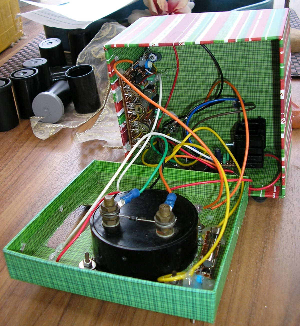
One thing in my build that contradicts the schematic is that LED1 is not used, but an LED is connected to the output of IC4, so that it is lit when the relay (and in turn the toaster oven heating elements) is turned on. This is effective as a power indicator as well as an indication of the output state. I would recommend following this design. As seen in the inside picture, I also put a 1N4004 diode between the panel meter + (connected to diode cathode) and - (diode anode) connections to discharge any inductive spikes. Plus I've put a fuse in series with the power input to protect against shorts. SW2 wasn't used, circuit power was connected directly to the voltage regulator output, with SW1 to turn everything on/off.
Veroboard layout, not including thermocouple amplifier or voltage regulator sections. Copper-side view.
The K-type thermocouple should be stuck to a circuit board (I use heat-resistant Kapton tape) in the oven so as to get an accurate reading because the boards will get hotter than the air temperature inside the oven. Similarly, because the boards are heated by infrared light from the heating elements, they should be placed directly on the wire frame, not on a tray. I used a cheap thermocouple from China with a yellow connector which was easily removed to reveal bare wires that can go into screw terminals. The insulation is coloured red on the side with the positive wire. Note that one of the thermocouples that I received had a broken weld so one of the wires at the end was loose, luckily I had ordered some spares as well.
As noted earlier, there isn't any feedback between the thermocouple amplifier and the controller so a common starting temperature should be reached by briefly turning the device on then turning it off and on when it reaches the starting temperature (I use around 20-30°C) to reset the timer and begin again from there. Of course a more elegant solution could easily be added, but this works well enough for me.
Once started, the controller will advance through the different PWM settings set by VR1-VR4, with the relative duration of the stages controlled according to the reflow profile in the graph above. The total duration of the cycle can be adjusted and potentially lengthened in order to allow for ovens that are unable to heat to the required temperatures in the "preheat" and "reflow ramp" stages. Ideally though, it should be adjusted so that the timing oscillator (IC2) runs at approximately 0.05Hz, and so the stages last for: 60s, 80s, 20s, 20s.
Initial calibration of the PWM settings will involve multiple runs, allowing the oven to cool down to the starting temperature between each. The temperature readings at the different stages (easily identified by the changed rate of relay clicking and "output on" LED (if fitted) blinking) should be noted, and adjustments made to VR1-VR4 in order to bring them closer to the targets in the reflow profile above, or as specified by the manufacturer of the solder paste to be used. The image of my tester shows a working configuration for my toaster oven (a relatively low-powered 600W model), and this might be a useful starting point. Note that stages 1 and 3 are set permanently on by rotating fully clockwise with the trimpots wired according to the verboard layout above.

At the end of the cycle, the "End" light indicates that the door of the toaster oven should be opened to allow the boards to rapidly cool. The temperature indicator can be monitored to see when they have cooled enough to be handled comfortably, before turning off the controller.

Due to the fumes produced during reflow, the oven should be used in a well ventilated space. Obviously the same oven should not be used for cooking food.
These are some potentially useful resources on the web for surface-mount reflow and related processes: